|
| Back to Main Page ----- Back to Chapter 2 |
|
2.2 CLEAN BALLAST TANK SYSTEMS AND PROCEDURES Tank ships which are not equipped with segregated ballast tanks (SBT)
may use their cargo system piping to take ballast into tanks reserved
from carrying cargo. These reserved, clean, ballast tanks (CBT), are
either original cargo tanks set aside for this purpose, or specially
constructed tanks. The original purpose of the CBT concept was to provide
an interim step between the earlier system of placing ballast in cargo
tanks, and the ultimate goal of requiring SBT for all tankers. CBT was
intended to reduce creation of oil and water mixtures on ships which: Some CBT tankers have a pump and line sections reserved for ballast. The ballast operation for these ships are a combination of CBT and SBT procedures. The CBT filling and discharge procedures involve several opportunities for a pollution incident if they are not conducted exactly according to approved procedures.
Case history In late 1990 a 57,000 DWT product/crude carrier arrived in Boston to off-load cargo. On arrival the ship requested a United States Coast Guard tank vessel examination letter. The previous letter has been withdrawn after a Coast Guard examination at Philadelphia revealed several deficiencies. That action was followed by two oil spills, after which the ship's crew was changed. In Boston five of the vessel's seven ballast tanks were found contaminated with oil. In addition, ballast was being carried in a centre tank, contrary to the IOPP certificate which listed the corresponding wing tanks for CBT. The ship's chief engineer confessed that he had pumped engine room bilges into the same centre tank. Further inspections revealed undocumented changes to the ballast system and inoperative ballast valves. Other ship systems were found in a similar state of disarray and disrepair. The vessel was denied entry into the port of Boston. The classifications society withdrew the ship's IOPP and SOLAS certificates. Local news media featured the vessel and its owners and operators on the evening news. The US Coast Guard began assessment of civil penalties for violations of MARPOL ANNEX I. The ship was issued a temporary certificate to depart on a one-way voyage to off-load its cargo, and then proceed directly to shipyard. Case analysis To say that the condition of this ship in the above case demonstrates deplorable management would be an understatement. Like the worst absentee landlords, the owners had obviously let the vessel deteriorate until it was a hazard to its crew and to the environment. It is possible that the vessel was being managed under a technical management contract instead of directly by the owner. Such an arrangement would not excuse the owner from his obligation to know the condition of his ship and correct significant defects. The most difficult position in this case is that of the master and crew. They find themselves employed on a sub-standard ship, in a foreign port, caught between clear and specific rules and requirements and an owner who refuses to provide the means for compliance. What should they do? The only thing to do in a case like this is to proceed as far as the condition of the vessel permits, then stop and advise the owner that operations cannot proceed because of the defects or conditions noted. The worst the owner can do is replace the crew. In this case, the vessel's officer's attempted to proceed with the defects unrepaired. For their efforts, they will have personal records in the US Coast Guard computer files, they will be reported to the authority which issued their licenses, and they were replaced! Something every ship's officer should understand is that no owner will support him if he has broken the law. Some officers bend or break pollution regulations because they think the savings of time or cost will be appreciated by the owner. In truth, any good owner would be appaled by such actions. The fines and penalties to which the owner may be exposed by the infractions of some well-meaning crew member far outweigh any possible saving. Conscientious owners expect that their crews will follow both laws and company policies with equal diligence as the best way of safeguarding the owner's interests. 2.2.1 Clean ballast systems 2.2.2 CBT operations in the discharge port 2.2.3 CBT manual Loading port operations. Extra or heavy weather ballast. Discharge port operations. Other operations. The following is an example CBT operation at the discharge port. The
system plan and valve numbering is the same as contained in the IMO
Dedicated clean ballast tanks guide (1982 edition, reprinted
1987). The instructions have been presented in a step by step fashion,
with illustration for each. CBT operations after cargo discharge is complete:
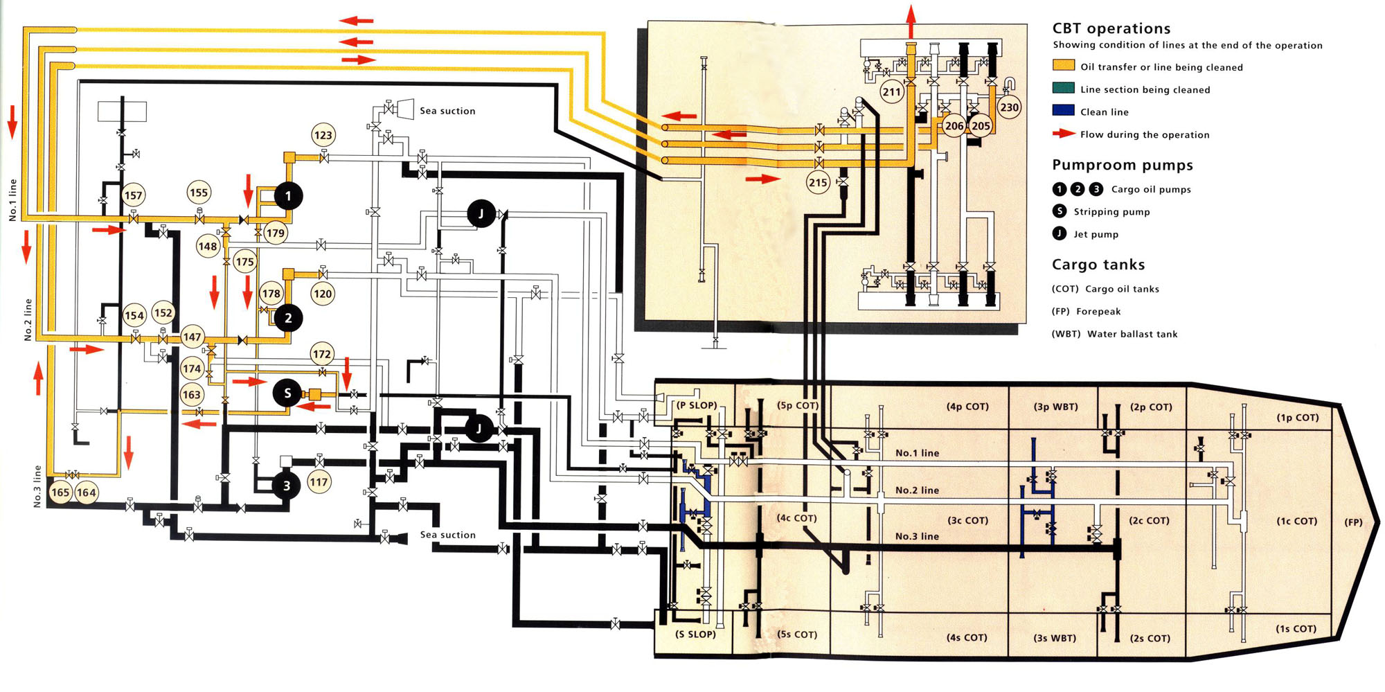 1 Open valves: 148 (No.1 pump discharge to jet pump), 175 (stripping suction to No.1 line), 179 (No.1 cargo pump stripping suction), 172 (stripping pump suction), 147 (No.2 pump discharge to jet pump), 174 (stripping pump suction to No.2 line), 178 (No.2 cargo pump stripping suction), 163 (stripping pump discharge valve), 164, 165 (stripping discharge to No.3 line), 205 (No.1 line manifold vent valve), 206 (No.2 line manifold vent valve), 230 (manifold vents inlet valve), (Valves 152, 154, 155, 157, 215 and 211 remain open from cargo discharge.) 2 Close cargo pump suction valves 117, 120 and 123. 3 Start the stripping pump. Continue to strip lines until pump loses suction. 4 Close valve 172.  Strip No. 1 bottom line ashore: 5 Open valves: 162 (stripping suction to pumproom suction crossover line), 122 (sea suction crossover block valve), 124 (No.1 pump suction crossover valve), 144 (No.1 line pumproom block valve), 104 (No.1 line pumproom bulkhead valve), 60, 59 (No.1 line block valves). 6 Start stripping pump. When stripping pump has developed a suction vacuum on No.l line, open valve 24 (No.1 centre tank main suction valve). The vacuum in the line will drain the length of the No.l line and the No.1 deck drop without allowing any cargo to fall back into the tank. 7 When stripping pump loses suction, stop the pump. 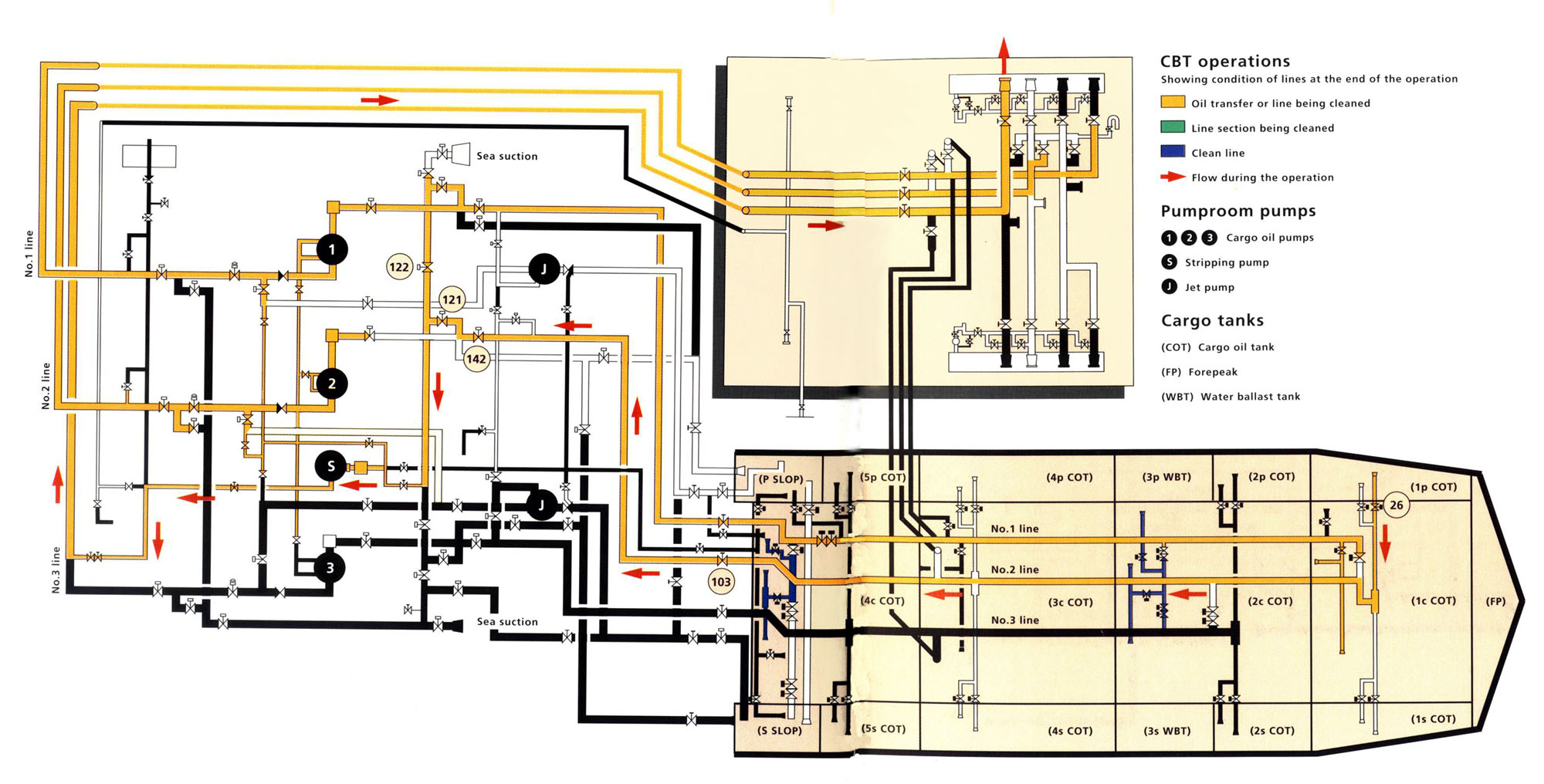 Strip No.2 bottom line ashore: 8 Close valve 122. 9 Open valves: 121 (pumproom crossover to No.2 cargo pump suction), 142 (No.2 cargo pump block valve), 103 (No.2 line pumproom bulkhead valve). 10 Start stripping pump. When a vacuum is indicated on No.2 line open valve: 26 (No.1 port cargo tank main suction valve). 11 When the stripping pump loses suction, stop the pump. 12 Close valve 26. 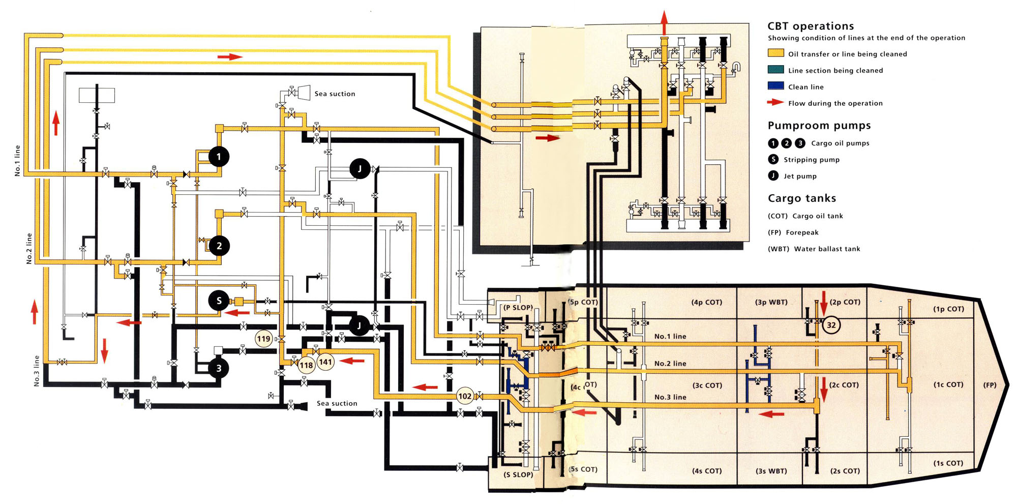 Strip No.3 bottom line ashore: 13 Open valves: 119 (sea suction crossover block valve), 118 (pumproom suction crossover to No.3 line), 141 (No.3 pump suction block valve), 102 (No.3 line pumproom bulkhead valve). 14 Start the stripping pump. When a vacuum is indicated on the No.3 line open valve: 32 (No.2 port cargo tank main suction valve). 15 When stripping suction is lost, stop the pump. 16 Close all valves. 3. Strip the No.3 pumproom riser and deck line to the starboard slop tank:
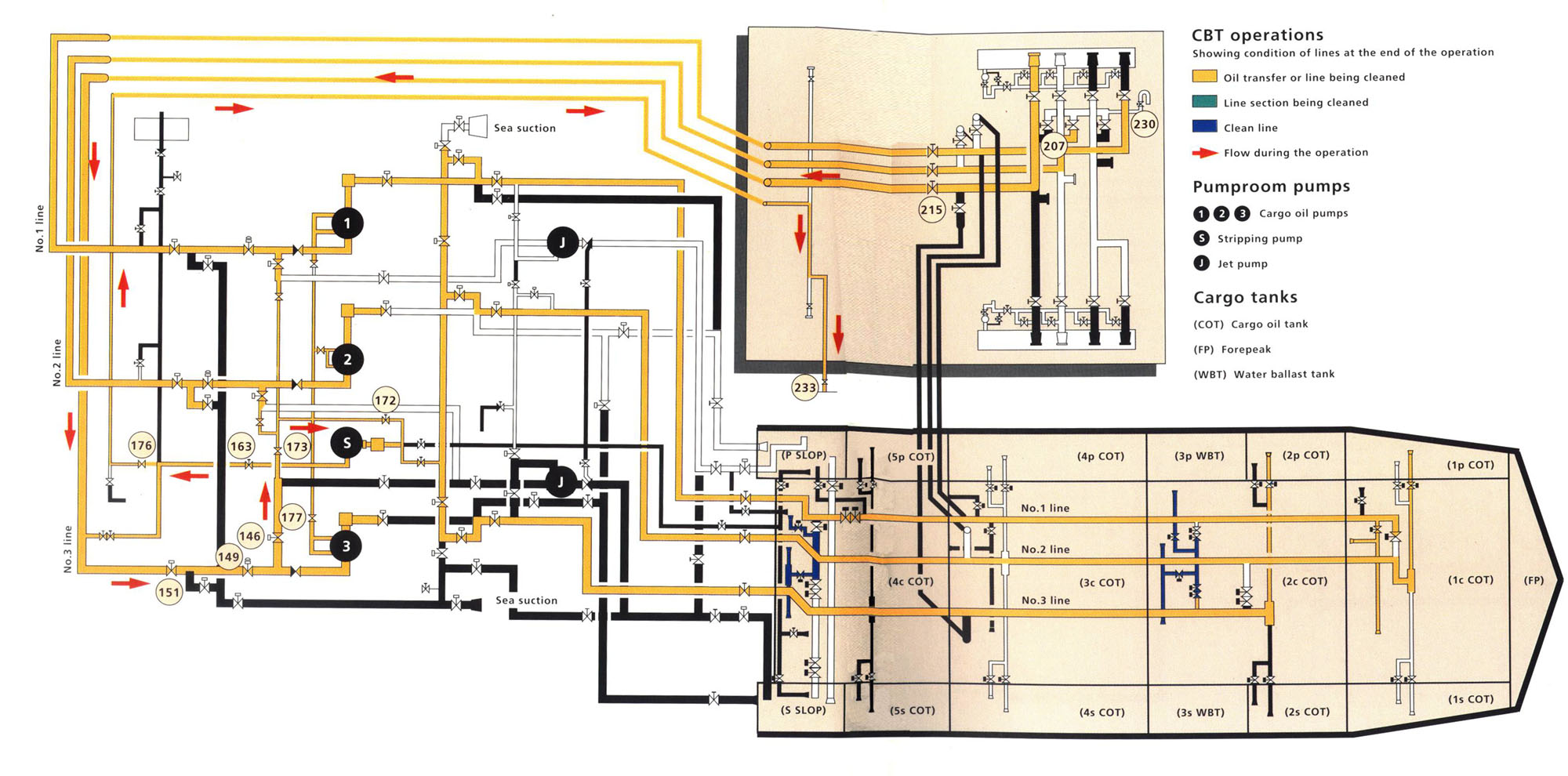 1 Open valves: 173 (No.3 to jet pump supply line stripper suction), 172 (stripping pump suction valve), 163 (stripping pump discharge valve), 176 (stripping pumproom riser valve), 233 (drop valve to starboard slop tank), 146 (No.3 pump discharge to No.3 jet pump valve), 177 (No.3 cargo pump stripping suction), 149 (No.3 pump discharge valve), 151 (No.3 line pumproom riser), 215 (No.3 deck line block valve), 207 (No.3 line manifold vent valve), 230 (manifold vents inlet valve). 2 Start stripping pump. When pump loses suction, stop stripping and close all valves. All residual cargo has now been removed from the ship's pipelines. The next step prepares the lines for receiving clean ballast by flushing them with retained ballast water from the CBT tanks. 4. Prime the No.l cargo pump
123 (No.1 pump suction valve), 144 (No.1 line pumproom block valve), 104 (No.1 line pumproom bulkhead valve), 60, 59 (No.1 line, block valves), 41, 40 (No.l to No.3 lines crossover block valves), 36 (No.2 centre rank stripping suction valve). 2 After one minute: close valve 36 (No.2 centre stripping suction), open valve 37 (No.2 centre tank main suction valve). 3 Wait thirty minutes (to allow the water to remove oil clingage from the pipeline walls). 4 Vent pump casing to insure pump is primed. 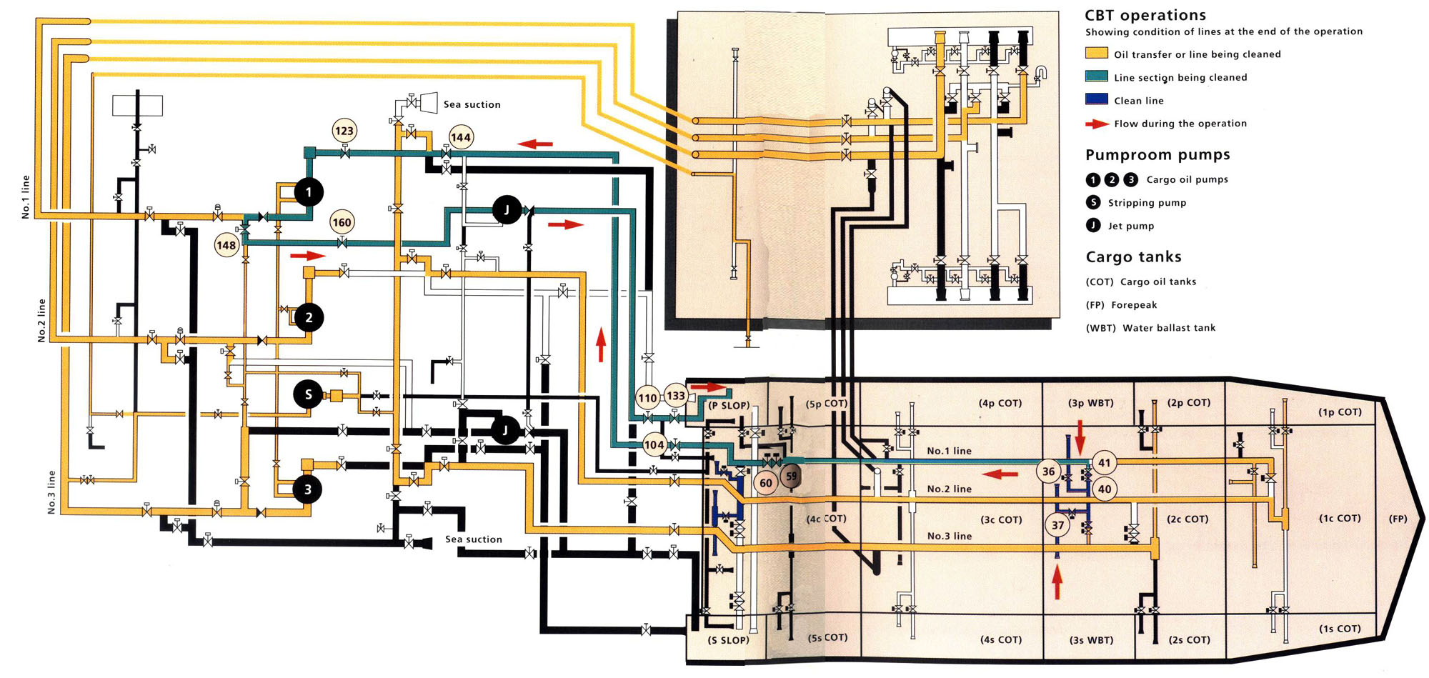 5. Flush No.3 centre tank branch line and No.1 main cargo line to port slop tank from No.2 centre tank:
148 (supply to No.1 jet pump), 160 (No.1 jet pump block valve), 110 (No.1 jet pump bulkhead valve), 133 (port slop tank fill valve). 2 Start No.1 pump and flush from No.2 centre tank main suction, via No.1 line, and discharging through the No.1 jet pump to the port slop tank. 3 Flush for three minutes. 4 Stop the No.1 pump. 5 Close valves: 37 (No.2 centre tank main suction valve), 40, 41 (No.1 line to No.3 line crossover), 59, 60 (No.1 line, block valves). 6. Flush the No.1 pumproom riser, deck line, and deck drop line from No.4 centre (ballast tank) to the starboard slop tank via No.2 line:
2 Open valves: 67 (No.4 centre ballast tank main suction valve), 58 (No.l line to No.4 centre tank suction block), 155 (No.1 pump discharge valve), 157 (No.1 line pumproom riser valve), 217 (No.1 line deck block valve}, 214 (No.1 line deck drop valve), 25 (No.1 line to No.2 line crossover valve), 103 (No.2 line pumproom bulkhead valve), 142 (No.1 pump suction block valve), 143 (No.2 line crossover valve to port slop tank suction/fill line), 111 (port slop tank suction/fill valve). (Note: valves 40, 41, 36, 37, 59, 60 and 156 are closed for this operation.) 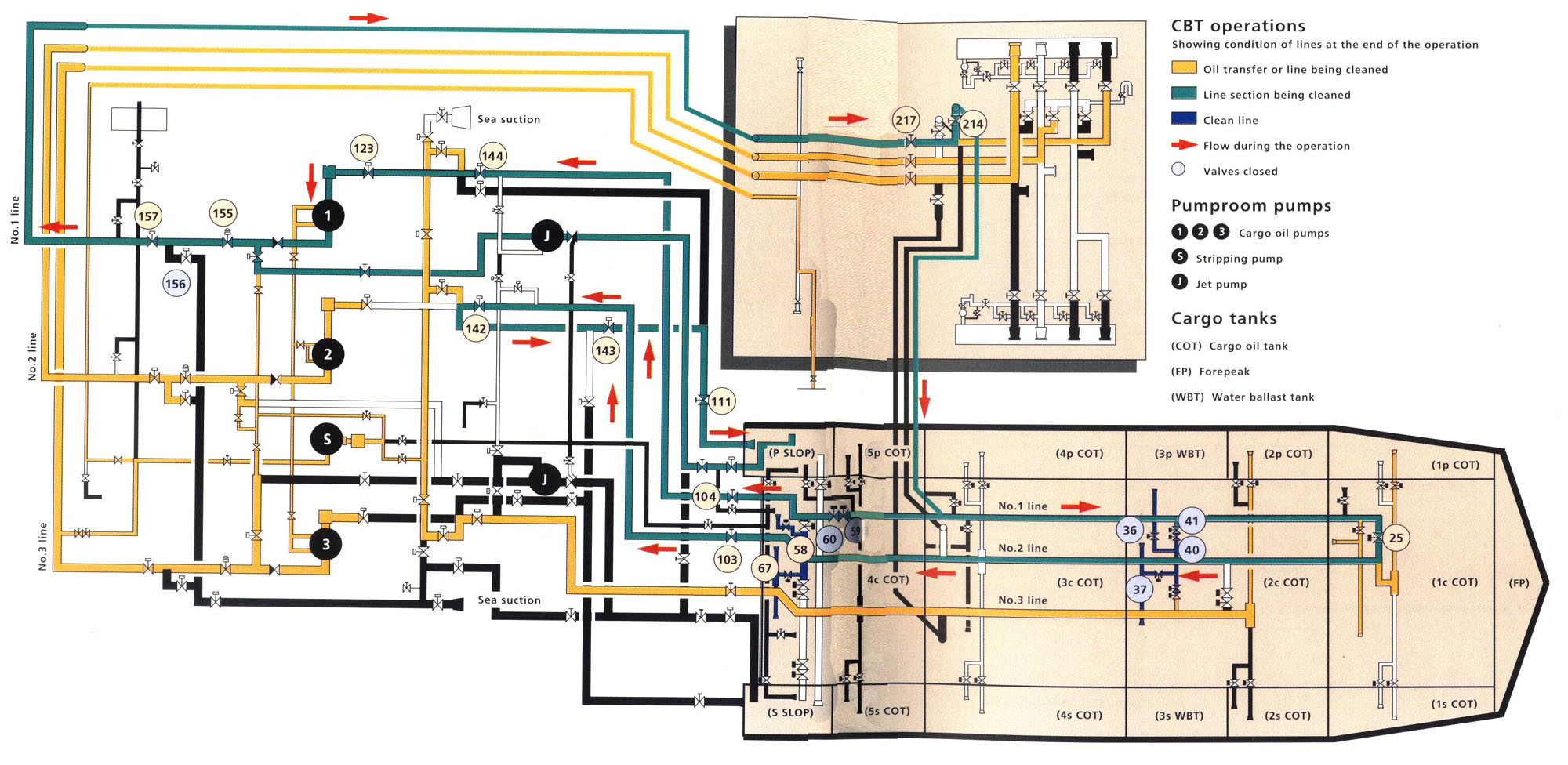 3 Start No.1 pump and flush at slow speed for thirty minutes from No.4 centre ballast tank, via pumproom risers, deck line, deck drop, No.2 line and pumproom into port slop tank. 4 Stop No.1 pump. 5 Close valves: 104 (No.1 line pumproom bulkhead valve), 144 (No.1 pump suction block valve). 7. Flush the ballasting line (No. 1 line) to the port slop tank from the sea: 125 (port sea suction block valve), 124 (No.1 line to pumproom crossover valve). 2 Start No.1 pump. 3 Open valve 126 (port sea suction). 4 Flush from sea via pumproom riser, deck line, deck drop No.l and No.2 bottom lines to port slop tank. 5 Stop the No.1 pump. 6 Close valves: 25 (No.1 line to No.2 line crossover valve), 103 (No.2 line pumproom bulkhead valve), 142 (No.2 pump suction block valve), 143 (No.2 line suction/fill to slop tanks), 111 (port slop tank suction fill valve). 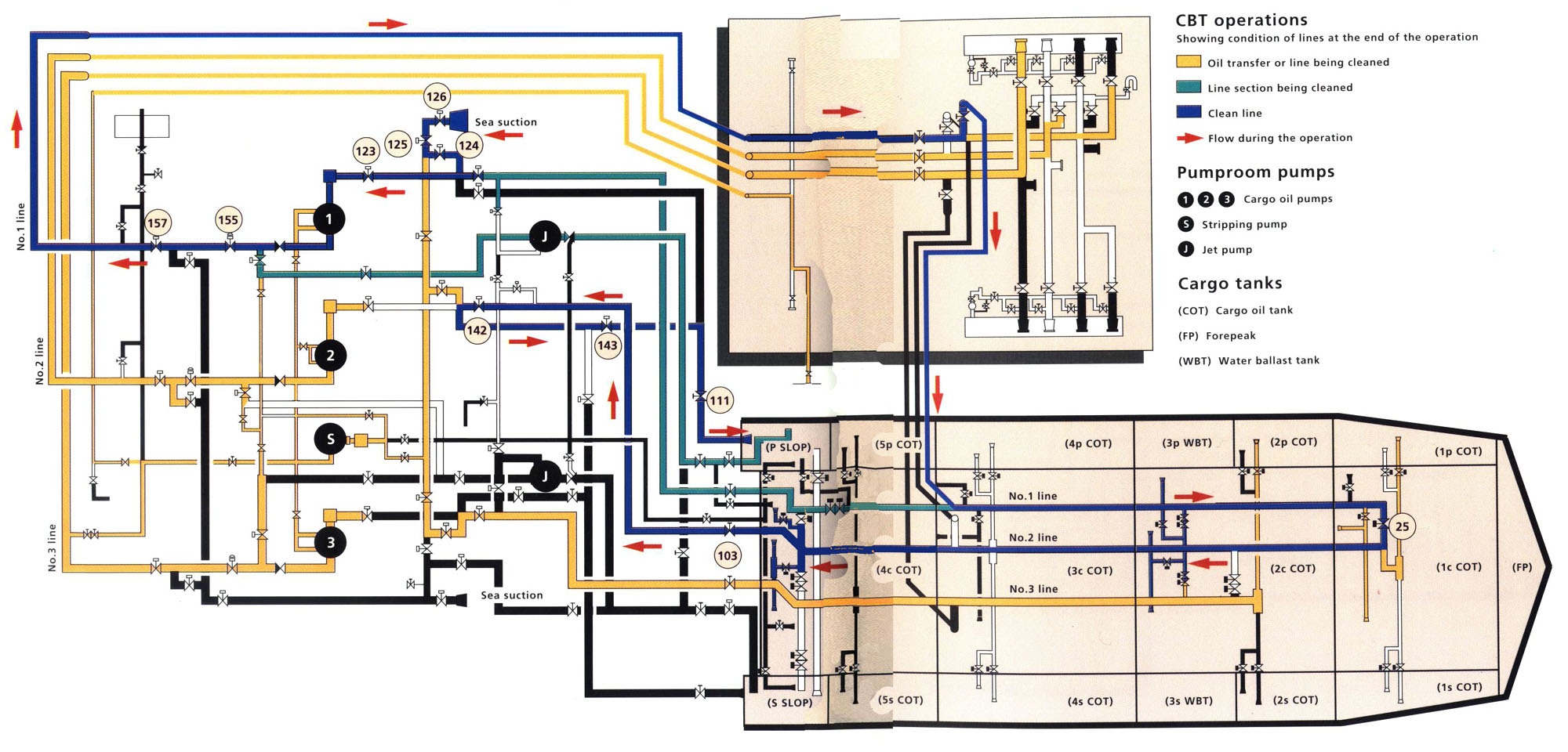 It should be noted that step 7 opposite is closely related to the old practice of taking ballast into cargo tanks. If the line flushing operation has not been properly conducted it also offers the same opportunity to create a pollution incident. Since the flushing operation is to a slop tank containing a quantity of water, there is a possibility of back flow when the sea suction valve is opened. The starting of the pump must be closely coordinated with the opening of the sea valve to minimise the opportunity for outflow through the sea suction.  7 Open valves: 59, 60 (No.1 line block valves), 104 (No.1 line pumproom bulkhead valve), 139 (No.1 line to pumproom suction crossover valve), 110 (jet pump discharge to slop and ballast tanks), 133 (port slop tank fill valve). 8 Start the No.1 pump. 9 Flush from sea via No.1 pumproom riser, deck line, deck drop, pumproom suction line, port jet pump, to port slop tank. Flush for three minutes. 10 Stop No.1 pump. 11 Close valves 104, 139, 110, 133. 12 Open valves: 37 (No.1 centre tank main suction valve), 67 (No.4 centre ballast tank main suction valve). Inspect No.2 centre and No.4 centre ballast tanks for presence of oil visually and with a hydrocarbon vapour tester, if oil is present tanks must be emptied and ' washed to slop tank and flushing sequence repeated. If tanks are free of oil, ballasting may proceed. 8. Ballast No.2 centre tank and No.4 centre tank from sea via No.1 line: 58 (No. line to No.4 centre tank suction and fill), 67 (No.4 centre tank suction and fill valve), 41, 40 (No.1 line to No.2 centre tank block valves), 37 (No.2 centre tank suction and fill valve), 2 Start No.1 pump. Ballast CBT tanks as directed. 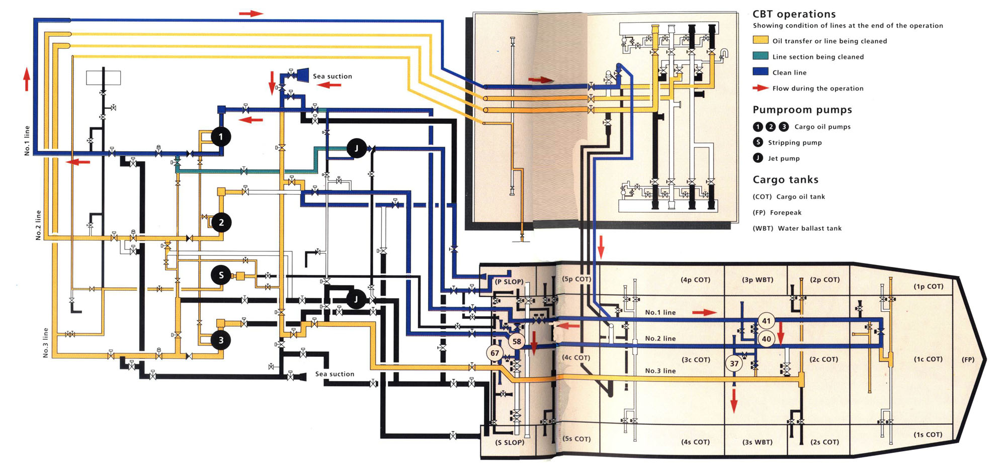
2.2.4 MANAGEMENT CONTRIBUTION TO POLLUTION-FREE
CBT OPERATIONS 2.2.5 Ballast records 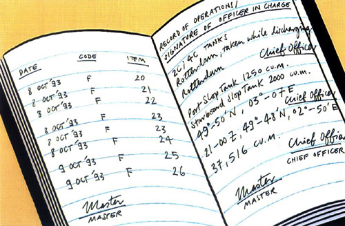 Oil record book entry for CBT ranker. All entries must include the times, tanks, and pipelines used for the ballasting operations, and the vessel's positions at the time of ballasting. |
| page top |