|
2.20 PREPARING THE LOADING PLAN
The loading plan for a tanker must address a multitude of requirements
including carrying capacity, hull stresses, loading and discharge instructions,
parcel separation, sequence of loading and discharge, vapour pressure,
expansion and contraction. A properly prepared cargo loading plan begins
with the most basic requirements and proceeds through a review of all
other essential considerations. The objective is to adequately ensure
the safety of the cargo at a minimum preparation expense in time, fuel
and effort.
In sections 2.8 and 2.9
the process for selecting a preliminary cargo layout was examined. By
the time the tank washing and tank cleaning operations have been completed,
the tanker should have received the final loading orders and any necessary
clarifications.
Loading orders may have been prepared in some detail by the owner's
or charterer's shore staff and may already represent the optimum loading
for the ship. Even detailed loading instructions must never be implemented
without careful review by the chief officer and master. The responsibility
for safe loading of the ship always rests with the master!
2.20.1 Loadline, loadline zones and loadline seasons
The International convention on loadlines, 1966, (with amendments
of 1971, 1975 and 1979), had the objective of establishing a uniform
set of requirements to prevent the overloading of ocean going vessels.
The desired outcome was the assurance that a ship would always leave
port with enough freeboard to provide the necessary margin of safety
against the weather and accidents which may be encountered during the
voyage.
The physical result of these agreements is the presence of the loadline
engraved on the side of each tanker. The practical implementation is
the chief officer's diligence in ensuring that the applicable loadline
is never submerged (on either side of the ship), when departing for
sea.
The chief officer must know exactly what draft is the limiting draft
when loading at and departing any given port. The complications are
the route of the ship, the season of the year and the salinity of the
water in the loading berth.
If the vessel is departing a port in a more restrictive zone (Winter)
and proceeding toward a less restrictive one (Summer) the ship cannot
be loaded below its Winter loadline mark. An example would be a tanker
loading at Valdez, Alaska and proceeding toward Panama. However, if
it is departing in a less restrictive zone and proceeding toward a more
restrictive one, it may depart with the limiting loadline immersed so
long as it consumes enough fuel to offset the immersion before entering
the more restrictive zone. An example would be a VLCC departing
the Arabian Gulf in November, bound for Rotterdam. The tropical loadline
applies at the time of departure, however the ship must have consumed
enough fuel and water by the time it passes the Mozambique Channel (20
degrees south latitude) that its summer loadline is not immersed and
enough additional fuel before passing Cape Torinana, Spain (44 degrees
north latitude) that its winter loadline is not immersed.
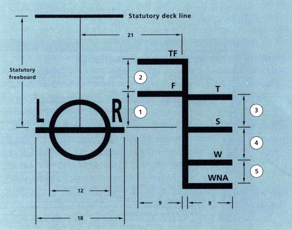
Load-line markings on the starboard side of an oil tanker.
1 Summer to fresh - ship's fresh
water allowance. 2 Fresh to Tropical fresh - one
forty-eighth of summer draft above fresh. 3 Summer
to tropical - one forty-eighth of summer draft. 4
Summer to winter - one forty-eighth of summer draft. 5
Winter to winter North Atlantic - for ships not more than 100 meters
(328ft) in length this distance is 50 millimetres (21 inches). For
other ships the winter north atlantic freeboard is the same as the
winter freeboard and is indicated only by 'W'. All measurements are
to be taken from the tops of the cross lines.
If the VLCC's tonnes per centimetre of immersion is 150 and the distance
between tropical and summer loadlines is 30 centimetres, then the tanker
would need to consume 4500 tonnes of fuel and water between the AG and
the Madagascar Channel in order to load to her full tropical marks on
departure. That is clearly impossible for even the thirstiest turbine
tanker! Nor would most ships be able to burn that amount of fuel between
the AG and Cape Torinana. The chief officer must therefore work backwards
from Cape Torinana, calculating the fuel burned to that point and loading
his ship to its Winter marks plus that amount. If the ship burns 60
tonnes per day and it is a twenty five day voyage to Cape Torinana,
then he can load to 10 centimetres over his Winter marks on departure:
60 tonnes/day x 25 days/150 tonnes/cm = 10 cm
This calculation must be done correctly, since the immersion of the
draft marks will be closely examined by port state control officers
on arrival and the fines for arriving with the ship overloaded will
be significant compared to the (approximately $3000), extra revenue
gained by loading another 10 cm.
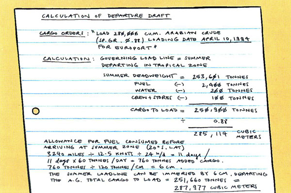
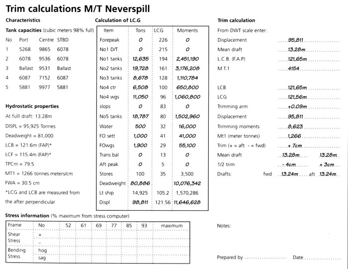
Calculation of departure draft and cargo quantity
where a loadline is the limiting factor.
The above calculation determinSes the deepest permitted draft from the
regulatory viewpoint. Other loading draft considerations include:
The available water depth at the loading berth.
Water density at the loading berth.
Depth of the departure channel and bar.
Depth over the bar at the delivery port.
Depth of water at the unloading berth.
Water density at the unloading berth.
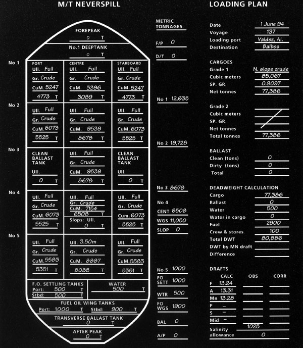
With the departure draft known, the chief officer can use the Deadweight
Scale (or tables), to determine the equivalent deadweight tonnage allowed.
That calculation determines the total tonnage capacity of the ship.
The quantity of fuel water and stores and ROB cargo anticipated to be
on board at departure is subtracted from the total deadweight to obtain
the tonnage of cargo to be loaded. On loaded passage, the fuel, water
and stores should always be the minimum required to safely complete
the voyage. If the loading orders, do not provide adequate fuel and
water allowance, owners/ charterers must be advised of the discrepancy.
2.20.2 Cargo allocation - draft, stress and trim
Cargo allocation may be indicated in the owner's/charterer's voyage
cargo orders received, especially if parcels of different products or
crude oils are to be carried. If the orders are for a straight cargo
(all one grade), allocation by tank will probably not be indicated.
For a straight cargo, the chief officer will multiply the tonnes of
cargo to be loaded by the cubic meters per tonne factor of the cargo
to determine the cubic meters of capacity required. He must then allocate
the cargo among the ship's tanks to provide the desired trim within
permitted hull stress factors.
The task of allocating the cargo and calculating the resulting trim
and stress is best done by a loading computer. The loading computer
saves hundreds of hours of chief officer time and effort yearly and
eliminates the arithmetic errors found in manual calculations.
Nevertheless, an officer must understand the basis of the calculations
to use the loading computer efficiently and there is always the possibility
that the computer will fail, leaving only the manual method available.
The steps for completion of a manual calculation are:
1 Trial allocation of cargo volumes to each tank.
2 Calculation of cargo tonnages in each cargo tank.
3 Calculation of fuel, water and stores for the voyage.
4 Calculation of total displacement for the voyage.
5 Calculation of trimming moments for the proposed
loaded condition.
6 Calculation of the longitudinal centre of gravity
for the proposed loading.
7 Determine the longitudinal centre of buoyancy for the proposed loaded
displacement (from hydrostatic tables).
8 Calculation of total trimming moments.
9 Determine the moment to trim one centimetre (or inch),
from the hydrostatic tables.
10 Calculation of trim (forward or aft).
11 Calculation of cargo/ballast allocation change necessary
to achieve the desired trim, using two or more cargo/ballast tanks.
12 Calculation of bending and shear stresses resulting
from the desired loading.
13 Calculation of bending and shear stresses for the
arrival condition at the discharge port.
14 If the stress factors are acceptable, determine
the ullages for loading of trim tanks.
15 Independent verification of calculations by another
officer.
The examples indicates that the initial allocation of cargo results
in a trim of 7 cm forward (by the head). The trim can be adjusted to
zero (even keel), by reducing the cargo quantity in the No.l cargo tank
by 45 tonnes and adding 45 tonnes of ballast to the afterpeak tank,
or by shifting 78 tonnes from the No.l cargo tank to the No.5 cargo
tank. The first alternative reduces total bending stresses more than
the second alternative. If the bending stresses for the first cargo
allocation are near the maximum allowable for sea conditions, then the
first alternative is the preferred option.
For a mixed cargo loading, the chief officer should begin with the
recommended cargo allocation contained in the loading orders, completing
the deadweight, trim and stress calculations accordingly. If the plan
works and makes best use of the vessel's capacity, then owners/charterers
can be advised that it is acceptable and will be followed. If the plan
does not work, ie. it causes excessive stress or trim, does not permit
proper segregation of cargo parcels, or if it causes deadfreight which
could be reduced by an alternative arrangement, then the master should
advise owners of the discrepancy and advise a suggested alternative.
The alternative may be rejected or accepted (due to reasons other than
the best use of the ship) and the master will proceed with the cargo
plan as agreed, provided it is safe to do so.
When cargo calculations are being performed manually, the independent
verification by a second officer is essential. A junior officer should
be assigned to independently do the verification. The verification task
gets the junior officer more involved in the cargo operation and aids
the development of his skills.
On conventional tankers, transverse stability is not a serious concern.
With most or all of the cargo tanks full, the transverse stability (as
represented by the metacentric height or 'GM'), is more than adequate.
On some combination carriers (ore oilers, bulk oilers, or OBO's), with
wide centre tanks, the number of slack tanks must be limited at loaded
draft to ensure adequate transverse stability. For those ships, transverse
stability must be calculated along with the trim and stress in the loaded
condition. Transverse stability in bulk carriers must be calculated
at several steps during the loading to ensure that the free surface
effects of the tanks being loaded do not create and unstable (negative
GM), condition. The calculation of transverse stability is an assumed
skill of all ships officers and will not be discussed here.
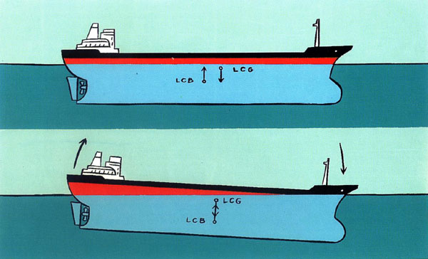
If LCB would be aft of LCG on an even keel, then
the ship will trim forward 'by the bow' until LCB moves under LGB.
The calculation of the cargo load should include a review of the arrival
condition of the ship at the discharge port. On some VLCC's it is necessary
to compensate for the consumption of bunkers to keep stresses within
safe limits. If loadline regulations allow, the required compensation
may be achieved by ballasting the after permanent ballast tanks or the
afterpeak. On other ships it may be necessary (with charterer's prior
authorisation), to transfer cargo so that the ship will arrive at an
even-keel trim. The stress conditions before and after the transfer
of cargo must be evaluated.
2.20.3 Separation, segregation and compatibility
The term 'compatible grades' means that two cargo parcels are similar
to the degree that they can be handled by the same pump and pipeline
system, after draining, without risk of contamination of either parcel.
Some cargo grades do not even require draining of pumps/pipelines between
parcels. When evaluating compatibility of cargoes, a number of critical
factors must be taken into account, including colour, flash point, pour
point, viscosity, specific gravity, sulphur content, lead content, gum,
water separation index, initial boiling point and vapour pressure (see
section 2.9.1). In addition, oil cargoes are classified
as 'clean' or 'dirty' according to their composition and handling characteristics.
Ships are normally restricted to carrying either clean or dirty cargoes
because of the risk of contaminating a clean cargo on a normally dirty
ship and the cost of trying to get a normally dirty ship clean enough
to carry a clean cargo. Between clean cargoes, flash point is the most
critical factor in terms of compatibility and special precautions must
be taken to prevent mixing between gasolines and other grades.
With dirty or black product cargoes, the question of flash point becomes
critical only when fuel oils are being carried with or after crudes.
Crude oil parcels must always be segregated from fuel oil parcels by
at least two valves, ie. 'double valve' protection.
Compatible grades can be loaded with single valve separation, provided
that the valve has been tested for tightness. This test is achieved
by applying liquid or air pressure on either side of the valve and observing
for leakage on the other side. The results of the test should be logged
and recorded in the maintenance journal/ program. Cargo operation should
be planned so that the separation valve(s) are not opened before the
contamination risk is passed at the discharge port.
Non-compatible cargoes must be completely segregated and cargo parcels
of different classes (ie. gasoline and heating oil), must be loaded
and discharged by separate cargo systems. Cargo parcels of the same
class, but of a different type (ie. two crude oils), may be handled
within a segregated cargo system.
On vessels with un-coated tanks, different grades must always be separated
by two closed valves (a master valve and a tank suction valve), due
to the possibility of the valve leaking from rust scale in the valve
seat. Ships which carry mixed parcels should pay special attention to
scale build-up underneath cargo valve discs. Scale accumulation may
prevent a valve from closing properly and result in a cargo contamination.
The problem of scale build-up is essentially eliminated in fully coated
tanks and single valve separation (with a master valve or a crossover
valve), may be permitted, provided there is program in place to regularly
verify valve tightness.
When planning the disposition of the various cargo parcels, care should
be taken to minimise the risk of contamination by undetected bulkhead
or pipeline leaks. If valve or bulkhead leakage is suspected, then the
adjacent grades must be loaded so that the more delicate product is
loaded to a smaller ullage (higher innage), than its neighbour. If the
more delicate product is a lower specific gravity (often the case),
then the difference in ullage must be large enough so that at the bottom
of the tank the delicate product still has a higher hydrostatic pressure
than the adjacent grade. If any leakage does occur, it will be from
the more delicate cargo into the less delicate cargo with less possibility
of that product being put 'off test'. The difference in ullage required
to provide for equal pressures at the tank bottom is:
U = D (H - L)/H
where:
U = ullage difference
D = depth of lighter parcel
H = heavier parcel sp. gr.
L = lighter product sp. gr.
This calculation yields the ullage difference required to produce
equal hydrostatic pressure at the bottom of adjoining tanks.
To provide a positive pressure from the lighter product tank into the
heavier product tank the ullage difference should be increased. Valves/hammerblinds
separating cargo parcels of different class should be sealed in the
loading port. These seals should not be removed until the cargo tanks
have been sampled at the discharge port and not until the first grade
of cargo has been discharged and the valve must be opened to complete
the cargo discharge.
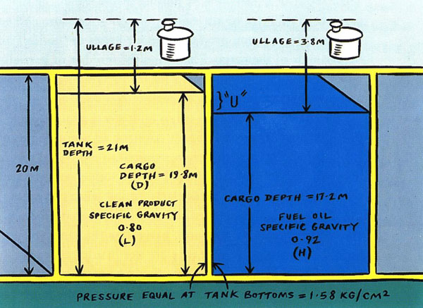
To prevent leakage of fuel oil to the clean product
cargo depth of fuel oil must be less than 80/92 x the cargo depth
of the clean product.
Most tankers are configured to provide some segregation capability,
with the normal number of parcel divisions corresponding to the number
of cargo pumps and main cargo lines on board. A tanker with three pumps
should have the capability of segregating three parcels, while one with
four pumps may be able to segregate four. The volume of each of these
segregations is fixed by existing bulkhead, valve and pipeline configurations.
For carrying mixed parcels on one voyage, the objective of charterers
or owners is to arrange the volumes of the parcels so that they most
closely fit the natural segregation capabilities of the ship. When an
exact match cannot be achieved, it is better to arrange the parcels
so that a tank is left empty in one section, than to risk a contamination
by loading one or more tanks beyond the natural segregation barriers
of the ship.
Another source of contamination is common or collected vent systems.
When non-compatible cargoes are loaded into segregated tanks which share
a common vent system, the cargo ullages must be large enough to prevent
any cargo from sloshing into the vent system while rolling, and flowing
into another tank.
If tanks are only partly filled, the movement of the vessel will cause
the cargo to move, or slosh, in the tanks. In some circumstances, such
as harmonic rolling, the sloshing can be violent.
This results in a breathing or pulsing inside the ullage space and will
cause the P/V valve to alternately relieve on pressure and vacuum. This
breathing action produces vapour losses or 'boil off of the lighter
ends of the cargo. Therefore, the number of partially filled tanks should
be minimised as a means of avoiding breathing losses and possible tank
structure or heating coil damage.
Recent developments in cargo tank stress analysis have indicated that
some cargo tank bulkheads constructed according to older class rules
contain less strength than required to withstand severe stresses imposed
by harmonic sloshing. This is another reason to minimise the number
of slack tanks, particularly during winter voyages.
When a vessel is directed to carry both heated products and volatile
(high vapour pressure), parcels on the same voyage, the cargo should
be arranged so that they are not in adjacent tanks. If this cannot be
avoided, the stowage should be arranged so that the products have only
one adjacent bulkhead and the temperature of the heated product must
not exceed 65 �C.
Some product carriers have sufficient pumps and pipelines to dedicate
one to each parcel of cargo carried. When other tankers carry multi-grade
cargoes, it is necessary to load or discharge similar grades of the
same class via the same pipeline/pump system, accepting some down-grading
(of the more critical product into the less critical product), in the
loading and discharge operations. Where it is essential that no co-mingling
or downgrading occur, a pump pipeline and tank system will be dedicated
exclusively to the parcel, at least until it has all been pumped ashore
safely at the discharge port.
A useful precaution when handling parcels requiring two-valve separation
and strict sequencing of loading/discharging is to apply temporary labels
to all of the valve actuators. If the valves are operated by hand on
deck, they can be labelled with 5 cm masking tape stretched across the
handwheel and marked with an indelible marker. If the valves are operated
from the cargo control room, small, clear plastic boxes should be placed
over the critical valve controls (fastened with tape if necessary) and
a 'white board' marker used to label the box with an appropriate notice.
For valves which must absolutely remain closed, a small sketch of a
severed hand is usually an effective deterrent!
2.20.4 Loading and discharging sequence
For straight cargoes, the loading sequence needs to consider only the
stresses placed on the hull by the cargo and the sequence in which the
cargo is likely to be discharged. Cargo tanks are normally loaded in
'sets'. The first set is selected to minimise hogging stresses on the
ship while bringing the ship close to an even keel condition. The second
set loads the ship evenly and bodily down to near the maximum loaded
condition. The final set, called 'trim tanks' are used to complete the
loading of the cargo to the vessel's marks and even keel (or if adequate
water depth exists in the loading port, to a departure trim which will
provide an even-keel arrival trim at the discharge port). On a vessel
with wing and centre tank arrangement, the centre tanks should be loaded
first, since the extra framing in the wing tanks makes them better able
to support the outward pressure on the longitudinal bulkheads. 'Checkerboard'
loading sequences should be avoided because such arrangements stress
the bulkhead intersections unnecessarily.
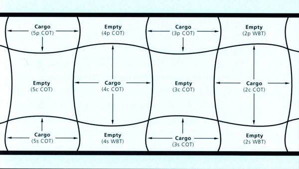
Alternating wing and centre ranks in the loading
pattern places tank bulkheads intersections under unnecessary stress
'Checkerboard' loading patterns should be avoided.
If the ship's designer has provided a recommended loading sequence
it should be followed whenever other cargo requirements permit.
Because of their slower state of decrease in ullage when topping off,
some chief officers prefer to use a centre tank rather than a wing tank
as the final tank to be filled. In that case, the centre tank to be
used for trim should be filled to 1/2 of its final ullage while loading
the other centre tanks, then stopped and reserved to receive the excess
flow while topping off the wing tanks. The loading can then be finished
in the desired centre or 'trim' tank. SBT ships require a closely integrated
loading and de-ballasting plan which minimises hull stresses during
loading.
Where multiple parcels are being carried in separate ship systems, the
primary considerations during loading are timing and hull stress. The
same stress criteria should be observed as with a straight cargo. However,
priority should be given to starting the grade of cargo which will take
the longest to load and to continuous loading of that grade (safety
permitting), until it is finished. Knowing which cargo will take the
longest requires information on shore loading rates which should be
requested by the master before vessel's arrival. This information may
be available on board from previous loadings at the same terminal. (See
section 2.20.5.)
Occasionally it will be necessary to carry two grades of cargo within
the same ship system. Such a procedure is never done without an element
of risk and the charterer should be advised of the master's objections
to doing so. Cargo parcels of different classes (i.e. heating fuel and
gasolines), should never be handled in the same system. Cargo parcels
of the same class but different type/grade (i.e. regular and premium
gasolines), may be handled in a single segregated system with proper
precautions.
Despite any objections recorded by the master, once orders have been
received to share a cargo system between grades, the vessel is still
responsible for making every effort to safeguard the cargo's quality.
For the loading operation, it is important to know which of the parcels
is the most delicate. With all the ship's pipelines clean and empty
before loading, the delicate cargo parcel should be loaded first and
blocked off as completely as possible in its tanks. The less delicate
parcel is loaded second. At the discharge port, the less delicate parcel
is discharged first. Then the pipelines are stripped dry and the more
delicate parcel is used to flush the lines into the shore line for the
first cargo. After the flush is completed, the shore lines are changed
and the delicate parcel can be safely discharged.
An alternative may be available if the two parcels are to share the
aft cargo system on the ship. With this arrangement, the less delicate
parcel is loaded first through the deck drop line and bottom lines,
into the forward tanks of the aft system. The bottom line block valves
between the two parcels are closed before loading begins. After the
first parcel has loaded the deck lines are carefully drained down to
the cargo tank, the deck drop valve is closed and the deck line block
valve is opened. The more delicate cargo is loaded second, through the
pumproom into the aft tanks of the system. At the discharge port, the
delicate parcel is discharged first, but not stripped. Any residue in
the tanks or pipelines is downgraded into the second parcel.
In dealing with loading sequences for shared systems, it is critical
to know the limiting cargo specification which is most subject to contamination.
If the limiting factor is colour, then the lightest parcel is the 'delicate'
one; if flash point, then the highest flash point product is delicate;
if lead, then the lowest lead content takes priority. Masters should
request guidance whenever they are in doubt regarding the sequence of
loading and/or discharging parcels in shared systems.
2.20.5 Critical path loading
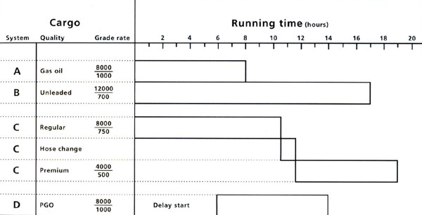
Bar chart loading plan for a multi-grade clean
cargo, loading Regular should be started as soon as possible and Unleaded
shortly after. Gasoil and PGO should be started as convenient but
so that they do not finish at the same time as 'B' or 'C' grades.
Reductions in cargo loading times are possible through a careful examination
of all of the activities associated with the loading operation and identification
of the connected series of actions which will take the longest to accomplish.
When the longest series has been identified, effort is focused on starting
the first action as early as possible and subsequently reducing the
'delay time' between each critical action to a minimum. The technique
is most useful on vessels, such as parcel tankers, which are scheduled
to load a series of products. The critical path may be determined by
the order in which the cargoes must use the ship's piping system, or
it may result from the order they will be received through the shore
piping. Identification of the critical path requires full information
concerning:
Volumes of each parcel to be loaded.
The loading rate of each parcel.
The sequence parcels will follow each other through a shore line or ship's
piping system.
This information can be converted to bar chart form, with a horizontal
time axis and a vertical ship/shore piping axis and the loading of each
parcel plotted as a time bar against the piping system to be used. Once
the time bars have been plotted, it is relatively easy to identify the
sequence which will take the longest: the 'critical path'. When the
critical path has been identified, the ship's officers must focus on
ensuring that the tank, piping and manifold to be used for the first
parcel of the critical path series are fully prepared when the ship
arrives at the loading berth. The corresponding hose/loading arm must
be connected first and immediately after the tank is passed inspection
for loading, the first parcel of the critical path can be started. When
the first parcel is nearly finished loading, all preparations must be
complete to start the second parcel. With the critical path under control,
the remainder of the cargo can be attended to in an organised, but less
urgent fashion.
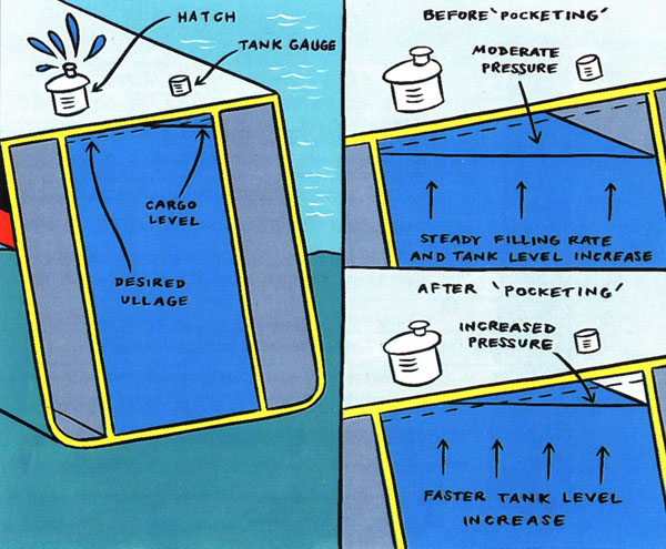
2.20.6 Ullage allowance
Company policy should dictate the minimum ullage to which the cargo
tanks may be filled. This should be a level at or below the 98% filled
level, or the level of the 'hi-hi' level alarm setting (if fitted).
To intelligently apply this guidance, the cargo watch officer must visualise
the location of the level sensors and level alarms in the tank and compare
this with the list or trim of the ship.
A very capable third officer once overfilled a centre tank in Houston.
The ship had a large port list. The mechanical gauge was located on
the starboard side of the centre tank and the tank lid, with open ullage
hatch, was located on the port side. Several centimetres before the
cargo reached to stop ullage on the tank gauge, a geyser of kerosene
erupted from the ullage hatch!
The cargo plan must allow for any expansion of the cargo to be expected
during the voyage. If there is insufficient ullage space, cargo expansion
due to increasing temperature can cause overflow with consequent oil
pollution, as well as possible structural damage.
If tank gauge is located at the high side of a
listed vessel an overflow may occur before final ullage is reached.
The same can occur if the ship has a large trim aft when topping off
and tank gauge is located forward in the tank.
A tank filling limit of 98% of capacity is generally considered adequate
for heated and non-heated grades alike. It allows room for cargo expansion
resulting from raising the product temperature by about 20 �C. However,
there are some occasions when an even greater ullage allowance may be
appropriate. The standard expansion allowance could be exceeded given
any one of the following conditions:
The cargo is loaded at a very low loading temperature, where an increase in
temperature of more than 20 �C can be expected on the voyage.
On voyages where exceptionally large variations in sea temperature are
to be expected.
On composite trading where un-heated products are stowed adjacent to heated
products.
An example would be a product tanker loading product at 10 �C. The
sea temperature en route may approach 28 �C. If the tank volume
is 3200 cubic meters, what is the required ullage at the loading port
to ensure a 12 cm minimum under-deck ullage at the discharge port?
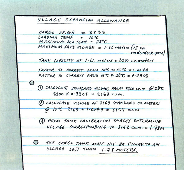
Where cargo temperature may increase during a
voyage the chief officer must calculate the necessary allowance for
cargo expansion.
In some cases, contraction of the cargo must be considered. Combination
carriers must maintain a minimum ullage in all tanks to prevent excessive
free surface and resulting unacceptable loss of transverse stability.
A combination carrier loading a warm cargo for delivery in a cold port
must fill each tank to a small enough ullage that all tanks remain above
the approved maximum ullage level when the cargo cools.
2.20.7 Written loading plan
When the chief officer has completed his review of all necessary factors
and checked his calculations, he prepares a written loading plan which
must include the following details:
Names of each grade of product or crude oil to be loaded and the quantity
of each.
Anticipated specific gravity and loading temperature of each grade of
cargo.
The cargo tank(s) each grade will be loaded into.
The pipeline system and loading path for each grade, including setting
of valves (identified by their unique identification numbers).
The sequence of loading of cargo grades.
The final ullage for each cargo tank.
The stand-by time required by the terminal for reducing loading rate or
stopping the cargo loading.
The anticipated departure draft.
Bunkers and ballast to be on board at departure.
Identification of all valves to be sealed closed before, during, or after
loading.
The maximum loading rates to be allowed and loading rate(s) expected with
the terminal.
Loading rate to be used for topping off tanks.
Special cargo procedures to be followed.
Special precautions with respect to moorings.
Equipment required (radios, ullage tapes, etc.).
Points in the loading when the chief officer is to be called or extra
manning is required.
Reference to standing orders for cargo operations.
Requirement that shore terminal regulations be read and signed by each
cargo watch officer.
2.20.8 Preparations for H2S
cargo
When the vessel is ordered to load sour crudes, the master must ensure that:
The vapour control system, including automatic tapes and vent lines,
is carefully inspected.
Self contained breathing apparatus is checked for condition and readiness
and the deck watch(es) are exercised in their use.
Pumproom lines, fittings and connections are checked for tightness and
any necessary repairs are completed before loading.
The portable H2S detector is in good operating condition. If sampling
tube testers are used, ensure that an adequate supply of test tubes
are on board.
|