|
5.26 CENTRIFUGAL AND DEEPWELL PUMP CHARACTERISTICS
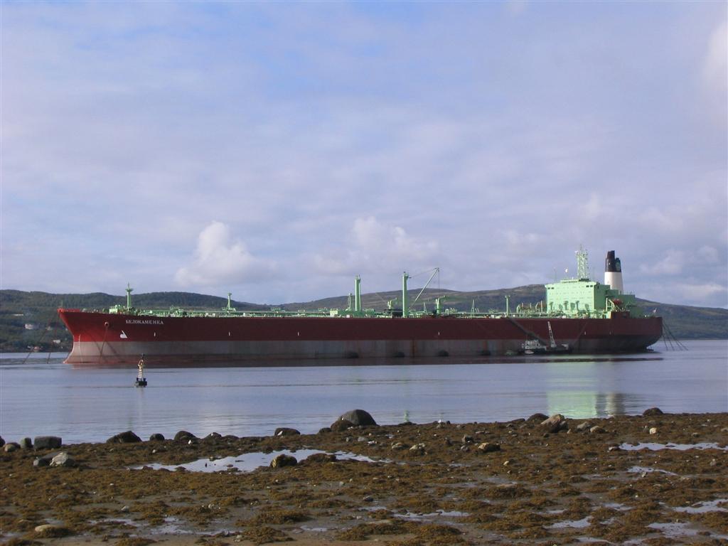
Section view of a two-stage centrifugal main cargo
pump showing flow.
The bulk of the cargo discharge will be done with the ship's main
cargo pumps. On most tankers the main cargo pumps are centrifugal pumps,
located at the bottom of a pumproom at the after end of the cargo tank
range and powered by a drive shaft from a turbine or electric motor
located in the engine room. Some smaller tankers and particularly chemical
or product carriers are fitted with deepwell centrifugal pumps in some
or all cargo tanks. While both of these pump types operate on centrifugal
force principles, their operation is quite different.
5.26.1 Centrifugal pumps
Centrifugal pumps are not self priming and will not operate efficiently
unless the cargo will flow freely to them by gravity. These pumps do
not 'suck' the cargo from the tanks. They expel the cargo from their
impellers, creating a void into which oil flows from the cargo tanks
under the force of gravity and atmospheric pressure. The pumps must
be carefully checked before starting to ensure that their chambers are
full of cargo. If the pump is started without filling the chamber it
can be 'burned out' in a matter of minutes, requiring an expensive overhaul
before it can be used again.
When the cargo discharge is started, the full cargo tanks provide adequate
positive head to move the cargo freely to the pump. As discharge proceeds
it is important to establish and maintain a good trim by the stern so
that the pump inlet remains below the cargo suction inlets in most or
all of the cargo tanks.
Once the cargo is flowing freely through the pump, they require little
attention, aside from regular inspections, until the tanks feeding them
reach a low level. Pumping problems may be encountered when the cargo
surface reaches the upper level of the tank bottom framing. While the
cargo level is above the frames it can flow freely over them and into
the section of the bottom framing containing the suction bellmouth.
Once the cargo level falls below the top of the framing, the cargo must
flow through the lightening holes and limber holes to reach the suction
pipe inlet. If the pump speed is not reduced before the cargo surface
reaches the level of the bottom framing, then the suction inlet framing
section will be quickly emptied and the pump will 'lose suction'. When
that happens the pump usually overspeeds and the turbine overspeed safety
trips the throttle closed, to the considerable annoyance of the engineer
(who is invariably doing some repair at the other end of the engine
room when this happens).
To avoid the embarrassment of explaining why the pump oversped, the
cargo watch officer must know the height of the ship's bottom framing
and slow down the pump while there is still a meter of cargo above that
level. The pump speed control and the pump discharge valve can then
be manipulated to maintain pump suction and cargo flow until the tank
is nearly empty. Main cargo pumps should not be used to drain the tank.
The stripping pumps are provided for that purpose. If a full cargo tank
of the same grade is available, its suction valve can be opened slightly
to 'feed' the pump until the low tank is reduced to stripping level.
Centrifugal pump performance is determined by a combination of factors
included on the following table, along with their range of values and
influencing factors:
| Factor |
Liquid column |
Remarks |
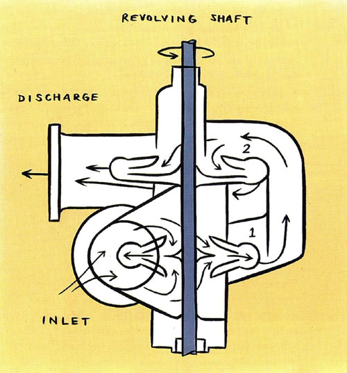
| Net positive suction head (NPSH) |
4 - 5 m |
Single stage pump; function of pump design and discharge rate |
| Pipeline friction (PLF) |
1 - 5m |
Tank distance from pump and discharge rate |
| True vapour pressure (TVP) |
5 - 9m |
Gulf area crude oils |
| Pump + line above bottom (-h3) |
2 - 2.5m |
Depends on ship design |
| Trim (+h2) |
0 - 3.5m |
Depends on location of tank and phase of the discharge |
| Liquid level (+h1) |
0 - tank ht. |
Depends on the phase of discharge |
| Atmospheric pressure (P) |
+/- 10m |
Depends on weather and IG pressure |
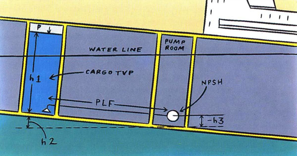
NPSH factors for a centrifugal pump.
If the values of these variables are known, pump performance can be
predicted by the following formulas (H = h1 + h2 - h3):
P + H > NPSH + LF + TVP - pump operating normally
P + H = NPSH + LF + TVP - pump begins cavitating
P + H < NPSH + LF + TVP - pump has no suction
Cavitation causes vapour bubbles to form in the pump as the cargoes
light ends boil off. The pump will make an audible (loud), rattling
sound and its speed and discharge pressure will fluctuate. If allowed
to continue, the cargo watch officer will shortly receive a call or
a personal visit from the chief engineer demanding to know why the cargo
pumps are being abused!
In some tankers the main cargo pumps are equipped with vacuum or vapour
extractors which can be used to enhance the draining capabilities of
the pumps. However, the most efficient (shortest), discharge will usually
be achieved by using the centrifugal pump for what it was designed to
do: move the bulk cargo. The stripping pumps should be used for their
designed function of draining the last of the cargo from the tanks.
5.26.2 Deepwell pumps
Deepwell pumps are centrifugal pumps designed to be mounted in the cargo
tank. They have a special application in chemical carriers, where each
tank is fitted with a dedicated pump. This improves the versatility
of the chemical or product carrier and minimises the possibility of
contamination that can occur when one main cargo pump is used to discharge
several products. Their design is best suited for refined products,
cargoes with viscosities of 1000 SSU or less (although products up to
2000 SSU have been pumped).
Because the number of pumps is larger, the individual pumps themselves
are smaller and individually require less power. This makes possible
the use of explosion-proof electric motors on the tanker deck as prime
movers for the pumps. Use of electric motors facilitates direct control
of pump start and stop functions from the cargo control room. Power
and load are indicated by volt and ampere meters in the CCR.
With a deepwell pump installation, the need for a pumproom is eliminated,
along with the hazards and complications of that space.
The modern deepwell pump is made up of a several centrifugal pumping
stages, mounted in series on a common vertical shaft. The shaft and
impellers are mounted at the lower end of a pump assembly column, which
is lowered into a deep cylindrical well (deepwell). In some installations
the bottom of the pump well is recessed into the tanker's double bottom,
providing a design which permits 100% drainage without use of stripping
pumps.
Modern deepwell pumps are self priming, so that they will take suction
from a full cargo tank even if they are started empty of liquid. The
self priming feature also permits stripping of cargo tanks to much lower
levels than is possible with standard centrifugal pumps. When a tank
has been discharged with a deepwell pump only a small, air operated,
reciprocating pump (mounted in the bottom of the tank), is needed to
strip out the residue and then empty the bottom of the cargo pump well.
The more common method of evacuating the deepwell is with an air or
nitrogen purge system. The gas is piped through a small-bore line at
the base of the pump and pushes the contents up the main discharge riser.
When a cargo tank is being stripped (or drained), with a deepwell pump,
the pump cycles as its self-priming function is activated, dropping
speed and pitch as it fills with liquid and then increasing in speed
and pitch as is loses suction and drops the contents of its discharge
column back into the well to re-prime itself. Pump speed should be reduced
when stripping (if speed control is available). If the pump is powered
hydraulically, it can be regulated to any speed desired to permit maximum
cargo recovery.
5.26.3 Screw pumps
Several 40,000 DWT product tankers have been fitted with gear or screw
pumps as main cargo pumps. This provides good cargo recovery with single
pump stripping ability, plus flexibility in the use or steam or electric
motors as the prime mover. Screw or gear pumps consist of two meshing
gears or screws which move the cargo between the pump casing and the
gears or screws teeth as the gears/screws are rotated. They are very
efficient and particularly suited for pumping high viscosity oils, such
as lubricating oils, or molasses.
5.26.4 Priming the pumps
Priming a deepwell pump is a simple matter of opening the pump well
suction valve and venting the upper level of the pump well to allow
the pumping stages to fill with liquid. Once a deepwell pump has established
suction, it will re-prime itself until the tank is completely empty.
Because of the re-priming feature, it is more difficult to damage the
pump by running it 'dry'.
Priming a centrifugal pump is a little more difficult. It must be carefully
filled with cargo before being started and when started must be carefully
checked to ensure that cargo is moving through it.
If suction is lost while discharging, a centrifugal pump will not re-prime
itself and the pump cannot normally be re-primed while running. It is
necessary to stop the pump before it can be refilled with cargo and
restarted. Centrifugal pumps are re-primed by stopping the pump and
opening the vent valve at the top of the pump casing. When the vapour
escaping from the vent line is replaced by a steady stream of cargo
the pump is primed and ready to restart.
If a centrifugal pump is fitted with a vapour/air extraction device
it should be placed in operation when the cargo level is low, before
the main cargo pump is expected to begin losing suction, and operated
continuously until the pump suction is finally switched to a full tank.
Centrifugal pumps depend on a continuous flow of cargo for cooling.
They can be quickly damaged due to overheating if they are run 'dry',
so they must be stopped as soon as it is suspected that suction has
been lost. The impellers operate on very small clearances within the
pump casing. If allowed to overheat, the impeller may contact the casing,
causing physical damage or additional friction, heat and an explosion.
|